Slide Wallet
A slim printed wallet with a novel card deployment mechanism.
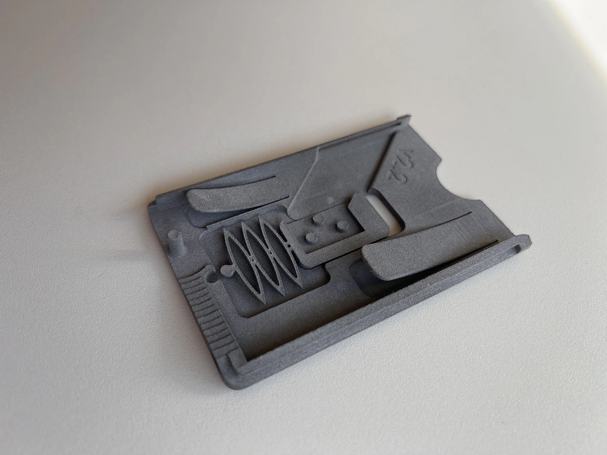
The wallet I have been using for several months
Design
The wallet consists of two halves which slide relative to each other to actuate the deployment mechanism. As the halves slide relative to each other, they cause a stepped armature (“swing arm”) to rotate and slide forward, ejecting the cards and fanning them out. Pushing the cards back into the wallet causes the deployment mechanism to backdrive and the wallet to close with the cards inside.
As the user pushes the wallet halves apart, a mechanism is actuated which disengages a retention latch which prevents the cards from sliding out when the wallet is not open.
A leaf spring constrains the cards against the lower surface of the wallet to ensure consistent deployment spacing and to prevent the cards from resting in the wallet diagonally, which could negatively impact the retention mechanism’s effectiveness.
Leaf spring
The leaf spring also causes the cards to be registered against the lower half of the wallet which corresponds to the longest section of the swing arm; this is important because if the cards are aligned against the other side of the swing arm, inserting new cards would cause the device to bind. (diagram below)
inserting new blue card between existing red cards:
top: cards aligned at top, binding
bottom: cards aligned at bottom, no binding


A small loop attachment point is provided at the back corner of the wallet, to allow accessories such as tracking devices or lanyards to be connected.
Kinematics
Cross section showing swing arm slightly sub-flush with lower housing
In order to prevent cards from getting caught between the swing arm and the lower housing, a slight pocket was designed into the housing so that the arm would be sub-flush with the surface the cards rest on. In order to minimize the size of this cutout, (and thus maintain as much rigidity as possible), it was necessary to determine the exact trajectory of various points along the swing arm. Since the cutout is on the lower housing (which is constrained to the swing arm only with a curved pin-in-slot), the trajectory in that reference frame was nontrivial. In order to solve it, I wrote a python script which used symbolic algebra to determine the path that each end of the swing arm would take relative to the lower housing. I had hoped that the parametric form of this equation could be used directly in Solidworks, but it proved to have too many terms, so a point-driven curve was generated which could then be imported to generate the cutout.
x(t) = 0.35*t - 0.13*(1.0 - 0.32*(0.38*t^2 - t + 5.0e-8*(t*(1.0e+15 - 3.8e+14*t))^0.5)/((0.22*(0.97 - (1.0 - (0.75*t - 1.0)^2)^0.5)^2/(0.38*t^2 - t + 5.0e-8*(t*(1.0e+15 - 3.8e+14*t))^0.5 + 0.66*(0.97 - (1.0 - (0.75*t - 1.0)^2)^0.5)^2) + 0.32*(0.38*t^2 - t + 5.0e-8*(t*(1.0e+15 - 3.8e+14*t))^0.5)/(0.38*t^2 - t + 5.0e-8*(t*(1.0e+15 - 3.8e+14*t))^0.5 + 0.66*(0.97 - (1.0 - (0.75*t - 1.0)^2)^0.5)^2))*(0.38*t^2 - t + 5.0e-8*(t*(1.0e+15 - 3.8e+14*t))^0.5 + 0.66*(0.97 - (1.0 - (0.75*t - 1.0)^2)^0.5)^2)))^0.5 + 1.6*(0.38*t^2 - t + 5.0e-8*(t*(1.0e+15 - 3.8e+14*t))^0.5)^0.5/((0.66*(0.97 - (1.0 - (0.75*t - 1.0)^2)^0.5)^2/(0.38*t^2 - t + 5.0e-8*(t*(1.0e+15 - 3.8e+14*t))^0.5 + 0.66*(0.97 - (1.0 - (0.75*t - 1.0)^2)^0.5)^2) + (0.38*t^2 - t + 5.0e-8*(t*(1.0e+15 - 3.8e+14*t))^0.5)/(0.38*t^2 - t + 5.0e-8*(t*(1.0e+15 - 3.8e+14*t))^0.5 + 0.66*(0.97 - (1.0 - (0.75*t - 1.0)^2)^0.5)^2))^0.5*(0.38*t^2 - t + 5.0e-8*(t*(1.0e+15 - 3.8e+14*t))^0.5 + 0.66*(0.97 - (1.0 - (0.75*t - 1.0)^2)^0.5)^2)^0.5) + 0.57*(0.38*t^2 - t + 5.0e-8*(t*(1.0e+15 - 3.8e+14*t))^0.5)^0.5 link3_y_str = 1.6*(1.0 - 0.32*(0.38*t^2 - t + 5.0e-8*(t*(1.0e+15 - 3.8e+14*t))^0.5)/((0.22*(0.97 - (1.0 - (0.75*t - 1.0)^2)^0.5)^2/(0.38*t^2 - t + 5.0e-8*(t*(1.0e+15 - 3.8e+14*t))^0.5 + 0.66*(0.97 - (1.0 - (0.75*t - 1.0)^2)^0.5)^2) + 0.32*(0.38*t^2 - t + 5.0e-8*(t*(1.0e+15 - 3.8e+14*t))^0.5)/(0.38*t^2 - t + 5.0e-8*(t*(1.0e+15 - 3.8e+14*t))^0.5 + 0.66*(0.97 - (1.0 - (0.75*t - 1.0)^2)^0.5)^2))*(0.38*t^2 - t + 5.0e-8*(t*(1.0e+15 - 3.8e+14*t))^0.5 + 0.66*(0.97 - (1.0 - (0.75*t - 1.0)^2)^0.5)^2)))^0.5 + 0.13*(0.38*t^2 - t + 5.0e-8*(t*(1.0e+15 - 3.8e+14*t))^0.5)^0.5/((0.66*(0.97 - (1.0 - (0.75*t - 1.0)^2)^0.5)^2/(0.38*t^2 - t + 5.0e-8*(t*(1.0e+15 - 3.8e+14*t))^0.5 + 0.66*(0.97 - (1.0 - (0.75*t - 1.0)^2)^0.5)^2) + (0.38*t^2 - t + 5.0e-8*(t*(1.0e+15 - 3.8e+14*t))^0.5)/(0.38*t^2 - t + 5.0e-8*(t*(1.0e+15 - 3.8e+14*t))^0.5 + 0.66*(0.97 - (1.0 - (0.75*t - 1.0)^2)^0.5)^2))^0.5*(0.38*t^2 - t + 5.0e-8*(t*(1.0e+15 - 3.8e+14*t))^0.5 + 0.66*(0.97 - (1.0 - (0.75*t - 1.0)^2)^0.5)^2)^0.5)
y(t) = 1.6*(1.0 - 0.32*(0.38*t^2 - t + 5.0e-8*(t*(1.0e+15 - 3.8e+14*t))^0.5)/((0.22*(0.97 - (1.0 - (0.75*t - 1.0)^2)^0.5)^2/(0.38*t^2 - t + 5.0e-8*(t*(1.0e+15 - 3.8e+14*t))^0.5 + 0.66*(0.97 - (1.0 - (0.75*t - 1.0)^2)^0.5)^2) + 0.32*(0.38*t^2 - t + 5.0e-8*(t*(1.0e+15 - 3.8e+14*t))^0.5)/(0.38*t^2 - t + 5.0e-8*(t*(1.0e+15 - 3.8e+14*t))^0.5 + 0.66*(0.97 - (1.0 - (0.75*t - 1.0)^2)^0.5)^2))*(0.38*t^2 - t + 5.0e-8*(t*(1.0e+15 - 3.8e+14*t))^0.5 + 0.66*(0.97 - (1.0 - (0.75*t - 1.0)^2)^0.5)^2)))^0.5 + 0.13*(0.38*t^2 - t + 5.0e-8*(t*(1.0e+15 - 3.8e+14*t))^0.5)^0.5/((0.66*(0.97 - (1.0 - (0.75*t - 1.0)^2)^0.5)^2/(0.38*t^2 - t + 5.0e-8*(t*(1.0e+15 - 3.8e+14*t))^0.5 + 0.66*(0.97 - (1.0 - (0.75*t - 1.0)^2)^0.5)^2) + (0.38*t^2 - t + 5.0e-8*(t*(1.0e+15 - 3.8e+14*t))^0.5)/(0.38*t^2 - t + 5.0e-8*(t*(1.0e+15 - 3.8e+14*t))^0.5 + 0.66*(0.97 - (1.0 - (0.75*t - 1.0)^2)^0.5)^2))^0.5*(0.38*t^2 - t + 5.0e-8*(t*(1.0e+15 - 3.8e+14*t))^0.5 + 0.66*(0.97 - (1.0 - (0.75*t - 1.0)^2)^0.5)^2)^0.5)
x(t) = 0.35*t - 0.13*(1.0 - 0.32*(0.38*t^2 - t + 5.0e-8*(t*(1.0e+15 - 3.8e+14*t))^0.5)/((0.22*(0.97 - (1.0 - (0.75*t - 1.0)^2)^0.5)^2/(0.38*t^2 - t + 5.0e-8*(t*(1.0e+15 - 3.8e+14*t))^0.5 + 0.66*(0.97 - (1.0 - (0.75*t - 1.0)^2)^0.5)^2) + 0.32*(0.38*t^2 - t + 5.0e-8*(t*(1.0e+15 - 3.8e+14*t))^0.5)/(0.38*t^2 - t + 5.0e-8*(t*(1.0e+15 - 3.8e+14*t))^0.5 + 0.66*(0.97 - (1.0 - (0.75*t - 1.0)^2)^0.5)^2))*(0.38*t^2 - t + 5.0e-8*(t*(1.0e+15 - 3.8e+14*t))^0.5 + 0.66*(0.97 - (1.0 - (0.75*t - 1.0)^2)^0.5)^2)))^0.5 + 1.6*(0.38*t^2 - t + 5.0e-8*(t*(1.0e+15 - 3.8e+14*t))^0.5)^0.5/((0.66*(0.97 - (1.0 - (0.75*t - 1.0)^2)^0.5)^2/(0.38*t^2 - t + 5.0e-8*(t*(1.0e+15 - 3.8e+14*t))^0.5 + 0.66*(0.97 - (1.0 - (0.75*t - 1.0)^2)^0.5)^2) + (0.38*t^2 - t + 5.0e-8*(t*(1.0e+15 - 3.8e+14*t))^0.5)/(0.38*t^2 - t + 5.0e-8*(t*(1.0e+15 - 3.8e+14*t))^0.5 + 0.66*(0.97 - (1.0 - (0.75*t - 1.0)^2)^0.5)^2))^0.5*(0.38*t^2 - t + 5.0e-8*(t*(1.0e+15 - 3.8e+14*t))^0.5 + 0.66*(0.97 - (1.0 - (0.75*t - 1.0)^2)^0.5)^2)^0.5) + 0.57*(0.38*t^2 - t + 5.0e-8*(t*(1.0e+15 - 3.8e+14*t))^0.5)^0.5 link3_y_str = 1.6*(1.0 - 0.32*(0.38*t^2 - t + 5.0e-8*(t*(1.0e+15 - 3.8e+14*t))^0.5)/((0.22*(0.97 - (1.0 - (0.75*t - 1.0)^2)^0.5)^2/(0.38*t^2 - t + 5.0e-8*(t*(1.0e+15 - 3.8e+14*t))^0.5 + 0.66*(0.97 - (1.0 - (0.75*t - 1.0)^2)^0.5)^2) + 0.32*(0.38*t^2 - t + 5.0e-8*(t*(1.0e+15 - 3.8e+14*t))^0.5)/(0.38*t^2 - t + 5.0e-8*(t*(1.0e+15 - 3.8e+14*t))^0.5 + 0.66*(0.97 - (1.0 - (0.75*t - 1.0)^2)^0.5)^2))*(0.38*t^2 - t + 5.0e-8*(t*(1.0e+15 - 3.8e+14*t))^0.5 + 0.66*(0.97 - (1.0 - (0.75*t - 1.0)^2)^0.5)^2)))^0.5 + 0.13*(0.38*t^2 - t + 5.0e-8*(t*(1.0e+15 - 3.8e+14*t))^0.5)^0.5/((0.66*(0.97 - (1.0 - (0.75*t - 1.0)^2)^0.5)^2/(0.38*t^2 - t + 5.0e-8*(t*(1.0e+15 - 3.8e+14*t))^0.5 + 0.66*(0.97 - (1.0 - (0.75*t - 1.0)^2)^0.5)^2) + (0.38*t^2 - t + 5.0e-8*(t*(1.0e+15 - 3.8e+14*t))^0.5)/(0.38*t^2 - t + 5.0e-8*(t*(1.0e+15 - 3.8e+14*t))^0.5 + 0.66*(0.97 - (1.0 - (0.75*t - 1.0)^2)^0.5)^2))^0.5*(0.38*t^2 - t + 5.0e-8*(t*(1.0e+15 - 3.8e+14*t))^0.5 + 0.66*(0.97 - (1.0 - (0.75*t - 1.0)^2)^0.5)^2)^0.5) y(t) = 1.6*(1.0 - 0.32*(0.38*t^2 - t + 5.0e-8*(t*(1.0e+15 - 3.8e+14*t))^0.5)/((0.22*(0.97 - (1.0 - (0.75*t - 1.0)^2)^0.5)^2/(0.38*t^2 - t + 5.0e-8*(t*(1.0e+15 - 3.8e+14*t))^0.5 + 0.66*(0.97 - (1.0 - (0.75*t - 1.0)^2)^0.5)^2) + 0.32*(0.38*t^2 - t + 5.0e-8*(t*(1.0e+15 - 3.8e+14*t))^0.5)/(0.38*t^2 - t + 5.0e-8*(t*(1.0e+15 - 3.8e+14*t))^0.5 + 0.66*(0.97 - (1.0 - (0.75*t - 1.0)^2)^0.5)^2))*(0.38*t^2 - t + 5.0e-8*(t*(1.0e+15 - 3.8e+14*t))^0.5 + 0.66*(0.97 - (1.0 - (0.75*t - 1.0)^2)^0.5)^2)))^0.5 + 0.13*(0.38*t^2 - t + 5.0e-8*(t*(1.0e+15 - 3.8e+14*t))^0.5)^0.5/((0.66*(0.97 - (1.0 - (0.75*t - 1.0)^2)^0.5)^2/(0.38*t^2 - t + 5.0e-8*(t*(1.0e+15 - 3.8e+14*t))^0.5 + 0.66*(0.97 - (1.0 - (0.75*t - 1.0)^2)^0.5)^2) + (0.38*t^2 - t + 5.0e-8*(t*(1.0e+15 - 3.8e+14*t))^0.5)/(0.38*t^2 - t + 5.0e-8*(t*(1.0e+15 - 3.8e+14*t))^0.5 + 0.66*(0.97 - (1.0 - (0.75*t - 1.0)^2)^0.5)^2))^0.5*(0.38*t^2 - t + 5.0e-8*(t*(1.0e+15 - 3.8e+14*t))^0.5 + 0.66*(0.97 - (1.0 - (0.75*t - 1.0)^2)^0.5)^2)^0.5)
(computer algebra parametric outputs)


Retention Mechanism
It was discovered during testing the leaf spring was insufficient to prevent cards from sliding out of the wallet under their own weight, even when not in the ‘deployed’ position. Increasing the spring rate on leaf spring was not a viable option as doing so made deployment more difficult, an effect which is exacerbated by the mechanical force disadvantage in the deployment mechanism.
The first lockout iteration used a flexure that would wedge the cards in when the wallet was closed, and deploy out of the enclosure during deployment, and in that position bend out of the way. This significantly improved card retention, but could still result in cards leaving the wallet if sufficient force was applied, since the cards would apply force directly into the slide spring.
Original retention/lockout design
In order to solve this problem, the next generation lockout design added orthogonality into the mechanism so that forces generated by the cards would not be transferred into the slide spring.
Updated retention/lockout design
Side Quest: Printed lockout return spring

Initial lockout designs used a print-in-place spring design to return the lockout to the closed position when not being actively used. The desired behavior was for the lockout to have some amount of spring preload holding it shut, so that a certain amount of force would need to be applied to the lockout before it started moving. A print-in-place spring which was printed with both ends fused to the lockout and upper housing would not achieve this, as it would start displacing as soon as enough force was applied to overcome friction.
Instead, the spring was printed too short, and then stretched to mechanically connect on the housing end, adding in some preload.
Current Work (Laser-Cut Inserts)

The fully printed design is functional (and has been my daily driver wallet for several months) but has several key shortcomings which must be solved before the project can be considered ‘complete’.
Firstly, the leaf spring has some creep issues and reduces in strength over the first several days of use. This means that the spring must either be sized such that the wallet works as design initially but eventually becomes too lose after several days of use, or must be designed to be initially overly stiff and break in over time. Furthermore, it means that if a wallet is eventually used with fewer cards than it was broken in with, the spring will not correctly recover and will apply the incorrect amount of retaining force. There is also a spring relaxation effect in the lockout slider return spring, although the effects in this case are less profound and easier to correct for.
Secondly, the overall wallet stiffness is lower than it should be, so excessive squeezing can cause the unit to bind during the deployment process.
The final version of the wallet uses laser cut metallic components to fix these issues. 1/16” stainless steel inserts will increase the panel stiffness, and the upper housing insert integrates a spring for the retention lockout. A spring steel leaf spring will replace the printed leaf spring.


The metallic leaf spring was sized using beam-bending hand calcs to approximate the stiffness of the printed spring, as-broken-in. The retention force it applies can be fine-tuned by adjusting its curvature, after laser cutting.
The spring integrated into the upper housing insert was sized using FEA to ensure that it would stay within the elastic region of SS 304 and have an appropriate spring rate.